SAG Mill Liners
Heavy-section shell, feed-end and discharge-end liners for semi-autogenous mills — the components that set how long your mill runs between relines.
The liner set, position by position
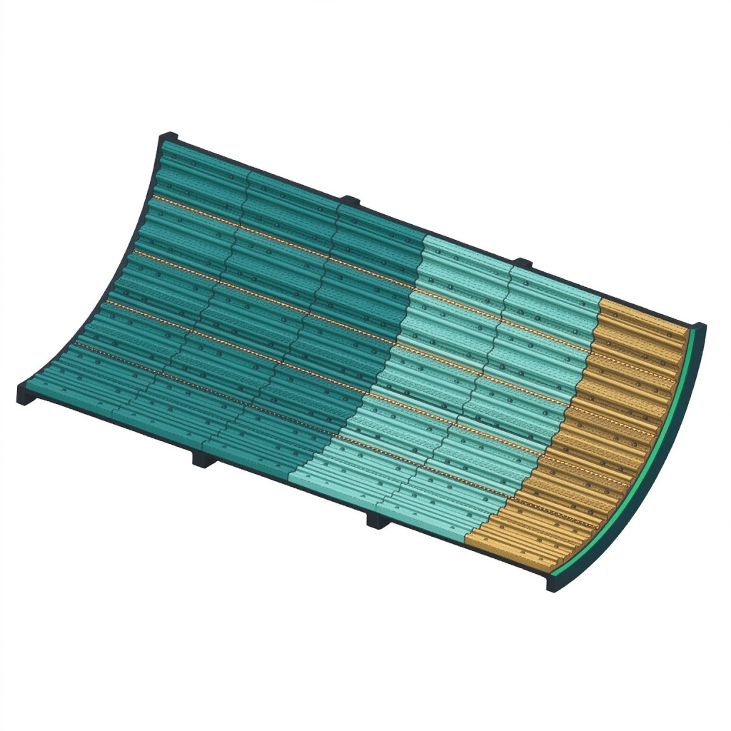
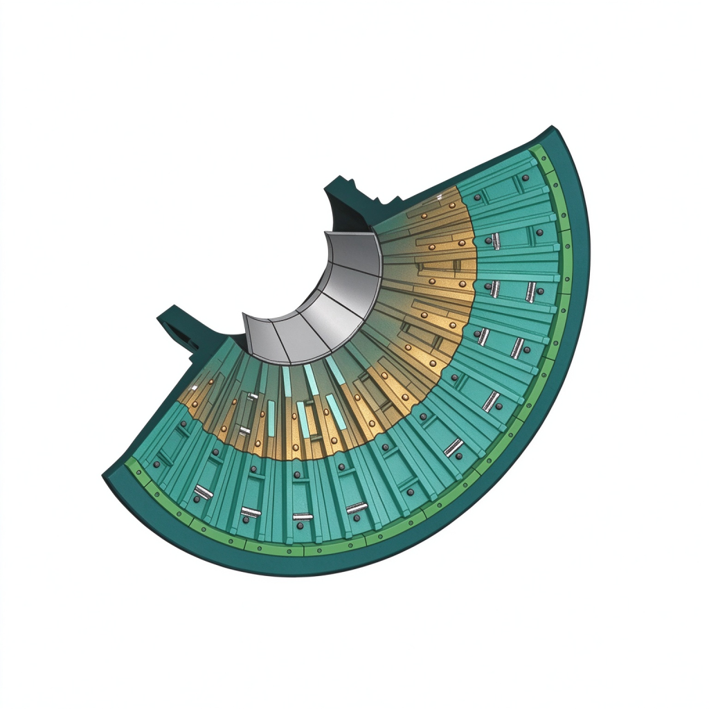
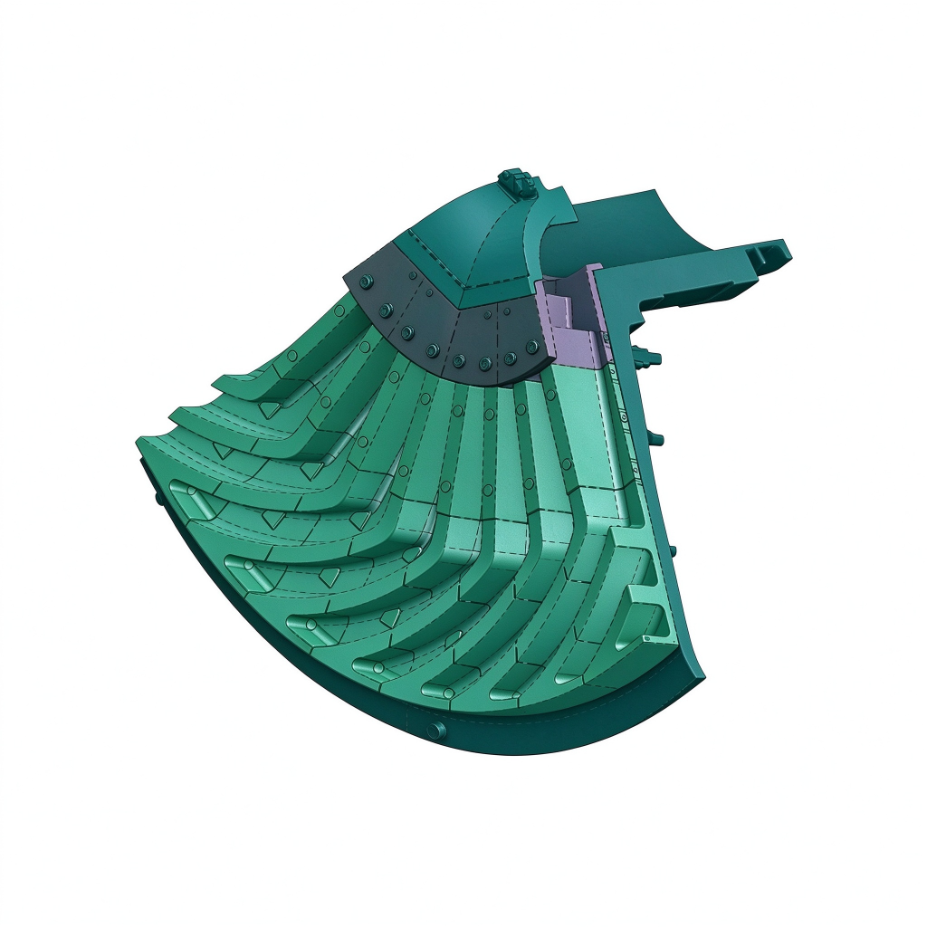
Three views of the liner set we cast for SAG and AG mills — shell plates, feed-end liners and the discharge system with its grate. Every position is cast to your drawing and quoted separately, so you can run different grades where the duty differs.
What a sag liner has to survive
Semi-autogenous mills are the hardest liner duty in a concentrator. The charge carries large ore plus grinding balls, so the shell sees impact and abrasion together, the feed end takes direct ore impact, and the discharge end has to move the pulp without eroding away. Sections are heavy, handling is difficult, and a wrong material decision costs weeks of production.
Where the wear actually comes from
Shell
Combined impact-abrasion from ore and balls. Uneven wear along the axis, fastest at the feed end.
Feed end
Direct ore impact at high velocity. Cracking and spalling on grades that are too hard.
Discharge end
Pulp erosion across grate plates and around pulp lifters; slot opening enlarges through life.
Pulp lifters
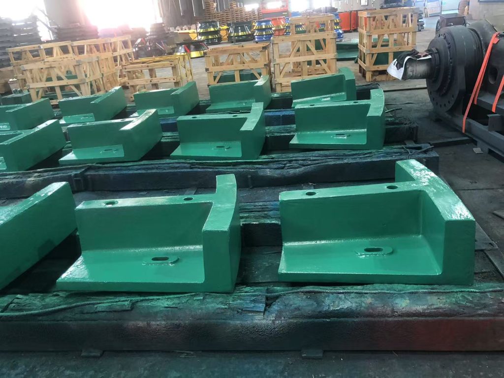
Severe sliding abrasion, often the first component to be replaced.
Recommended material by position
In practice the right answer is usually a mix within the same mill. This table is a starting point — your drawing and your wear history decide the final call.
| Position | Dominant wear mechanism | Recommended material |
|---|---|---|
| Shell — coarse end | Heavy impact + abrasion | Mn18 / Mn18Cr2 |
| Shell — fine end | Abrasion dominant | Cr-Mo alloy steel |
| Feed-end head | High-velocity ore impact | Mn13 / Mn18 |
| Discharge-end head | Impact + slurry erosion | Mn18Cr2 |
| Grate plates | Pulp erosion, slot wear | Cr-Mo / Mn18Cr2 |
| Pulp lifters | Sliding abrasion | Cr-Mo alloy steel |
The complete SAG liner package
Typical manufacturing envelope
- Mill diameter4.0 – 12.0 m
- Liner thickness60 – 200 mm
- Single piece weight150 – 4,000 kg
- MaterialsMn13, Mn18, Mn18Cr2, Cr-Mo
- Casting toleranceISO 8062 D1 / GB-T 6414
- Non-destructive testingUT / MT on request
If your liner falls outside the ranges above, send the drawing anyway — we will tell you honestly whether we can cast it and how.
Send your drawing — we do the rest
What we need from you
Send the drawing and we can quote. If any of the items below are missing we will tell you what is required before the pattern is cut — the earlier the question is asked, the cheaper the answer.
- 2D drawing (DWG or PDF) or a 3D model (STEP / IGES)
- Material grade and required hardness, if specified
- Quantity per position and whether a full set or part set
- Bolt hole pattern, bolt size and grade
- Mill make, model and diameter (helps us sanity-check the drawing)
- Current liner life, if you are replacing an existing set
From drawing to documented casting
Drawing review
We check the drawing for castability, confirm the material and flag anything that would cause a problem at the foundry — before a pattern is made.
Pattern and moulding
Pattern built to your drawing with the correct shrinkage allowance for the specified grade.
Melting, casting, heat treatment
Chemistry verified by spectrometer before pouring; heat treatment logged with furnace records.
Inspection and despatch
Dimensions verified against the drawing, documentation compiled, castings crated for shipment.
Common questions
Can you cast SAG liners to 4 tonnes per piece?
Yes. Our melting and heat treatment capacity covers pieces up to several tonnes. Send the drawing and we will confirm casting weight, pattern cost and handling arrangements.
How do you control wear at the feed end?
Usually by keeping manganese in that position and reviewing the lifter profile with you. Increasing section locally is often more effective than changing the whole casting to a harder grade.
Can you supply a partial set?
Yes. Many customers start with the position that wears fastest. Supplying one position at a time is normal practice and does not affect how we document the order.
Can I visit the foundry before ordering?
Yes, and we would rather you did. Tell us when you plan to travel and we will arrange the visit in Dangyang, Hubei — including inspection records for orders already in production.
Send us your drawing — get a quote within 24 hours
Upload DWG, PDF or STEP files. Our engineers review every drawing and come back with a technical reply and a firm quotation — no obligation.